Setting up the PID Controllers
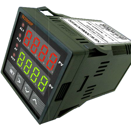
After completing the Circuit Panel, the PID controllers can be setup and partially tested before final installation of the Circuit Panel and modified burner. In this example the N2006P PID controllers are used. Other PID controllers may be similar. These were obtained from EBay.
First. turn off the main power toggle switch and the individual PID controller switches before connecting any power to the Circuit Panel.
Also disconnect the heating elements from the Circuit Panel if they were hooked up already. Also, be sure to at least connect the PT100 type thermocouple used in the Preheat Tank and if possible, the K type thermocouple used in the Nozzle Block - even if it's not in the block.
Information about these PID Controllers is located in this PDF and should be read before proceeeding. If you don't understand it, thats OK as you can proceed with the steps below to get it setup, but it is best to try to understand how it works first.
1. Power switches are off and no power is supplied. Connect only the White & Black wires that supply the main power to the Circuit Panel.
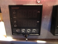
2. Turn on the main power switch on the circuit panel and then the PID that controls the Preheat tank. The PID controller should light up and values, not necessary matching these, will be displayed. The first display line is the temperature of the PT100 theremocouple if properly connected. More about that later. This is known as the Process Value or PV. The second line displays what is known as the Set Value, or SV, which we will set later on. Typical PID controller value is 80.0 for the N2006P PID controller.
3. Next we need to setup some parameters. Press the SET button.
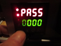
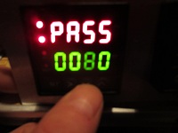
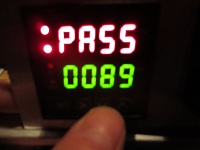
4. Next, a password has to be entered to get to the menu we want to use. The password is 0089. Press the RIGHT ARROW button twice to get over to the 2nd digit so you can change it to a value of 8. The value can be changed by pressing the UP or DOWN ARROW buttons the appropriate number of times. Just press the DOWN button twice so it changes from 0 to 9 to 8.
5. Now press the RIGHT ARROW button to move over to the last digit location and change it by pressing the DOWN ARROW once.
6. Now press the SETUP button and you will be in the menu we want to use.
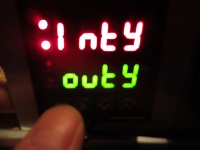
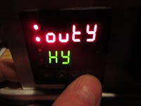
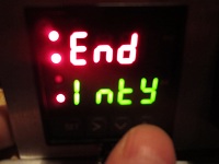
7. You are now at the first item in the Menu. Press the SET button to change this value. Please refer to the PDF document mentioned earlier. Inty is the Input Type and refers to the type of thermocouple. The typical default is PT100 and that is what we want. If PT100 is not displayed then use the UP or DOWN ARROWS to scroll through a selection of theremocouple types until you get PT100.
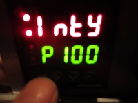
8. Once you have PT100 displayed then press the SET button to return back to the menu and then press the UP ARROW once to go to the next menu item. While in the menu, you will notice the current menu item is the first line and the next menu item is listed on the second line. To get to the next item, you press the UP ARROW, otherwise you can press the DOWN ARROW to go backwards in a menu.
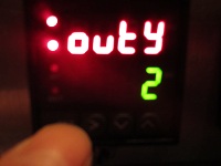
9. Again, press SET to change this menu items value. The typical default is 2 and that is what we want since we are using an SSR instead of the PID's internal relays. Once 2 is displayed, press SET and you'll be back in the menu.
10. Scroll to the next item (UP ARROW) and you should see the following (or you may see Atdu displayed instead). We will not change the factory default value for this item. Should you want to look at it, it may have the default value of 3 or 10, but just go back to the main menu.
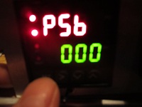
12. Once back in the main menu, scroll to the next item as shown. Check this value and make sure its set to 0, then return to the menu
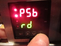
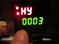
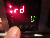
13. Now scroll to the next menu item rd. The value of the rd menu item determines whether we are using the PID to heat or cool. Be sure this value is 0 (heating) and then return back to the menu.
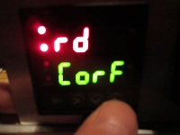
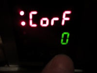
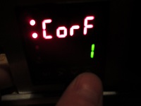
14. Now scroll to the next menu item and check the CorF value at set it to 0 if you want the temperature to be displayed in degrees Celcius or 1 in Farhenheit. Then return back to the menu
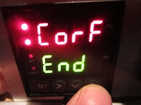
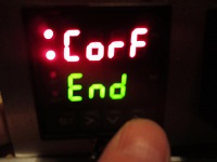
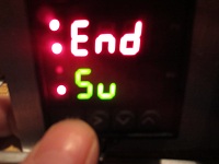
15. The next menu iem is END. Scroll to this item. The menu is exited by pressing the SET button when you have END displayed as the current menu item.
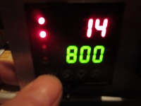
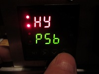
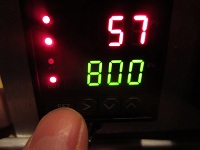
16. Now you are back to a normal display with the PV and SV values being displayed. If the thermocouple is connected correctly you should see the PV equal to the temperature of the probe. In this case, my probe was at 57 F.
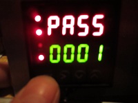
17. Now that PV is setup, the next thing to do is setup the SV value as well as some other PID settings by using the SV and Alarm Parameters menu. This menu is entered by using the 0001 password.
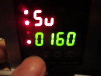
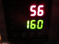
18. The first menu item is the SV which we want to set to 160F. In the last menu I selected temperatures to be in Farhenheit.
Dec 26: 2014 I'm typically using 140F now for this setting when using vege oil.
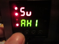
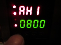
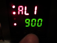
19. The next menu item is Alarm High 1. Take note of the default value, which in this particular example is a default of 80.00. Go back to the main menu and go to the next item AL1
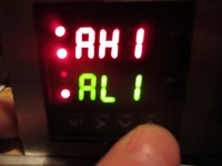
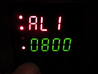
20. AL1 is the Alarm Low 1. We want to set its value to be the same as AH1 so that we disable it. Go back to the main menu and to the next item.
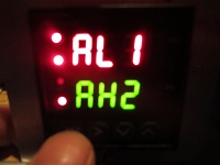
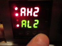
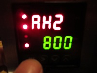
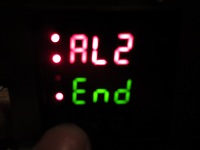
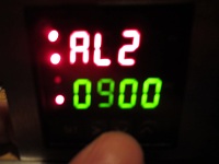
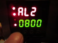
21. Next we want to take note of the value of AH2 and then go to the next menu item and set AL2 to be the same.
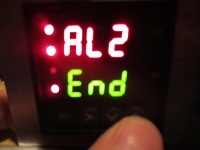
22. Now go to the next menu item, END, and press the SET button to return to normal display where you will now see the desired SV displayed.
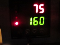
23. By placing your hand on the PT100 (Preheat Tank) thermocouple probe, you should be able to increase the temperature if it's much lower than your body temperature. I was able to increase mine about 20F in less than a minute.
24. The above procedure can be repeated with the other PID controller. It will need to be set to use a K type thermocouple, with an SV (Set Value) equal to 300F whcih is the desired temperature for the nozzle block.